Prodigy Brake Controller Instruction Manual: A Comprehensive Guide
This manual details the installation‚ operation‚ and troubleshooting of Tekonsha Prodigy P2 and P3 brake controllers‚ utilizing motion and inertial sensor technology for proportional braking․
The Tekonsha Prodigy brake controller is a vital safety component for anyone towing a trailer equipped with electric brakes․ Designed for trailers with one to four axles‚ the Prodigy utilizes advanced technology to ensure smooth‚ controlled braking‚ mirroring the driver’s braking input․ Unlike older systems requiring manual adjustment‚ the Prodigy‚ particularly the P2 and P3 models‚ automatically adapts to varying terrains and trailer loads․
Key features include proportional braking‚ achieved through sophisticated motion or inertial sensing‚ and a manual override function for situations demanding maximum stopping power․ Understanding the specific model – P2 or P3 – is crucial‚ as they differ in sensing technology․ The P2 employs motion sensor technology‚ while the P3 utilizes an inertial sensor for enhanced responsiveness․ Proper installation and calibration‚ as outlined in this manual‚ are essential for optimal performance and safety;
Understanding Electric Brake Controllers
Electric brake controllers are essential for safely towing trailers with electric brakes․ They translate the driver’s braking action into an electrical signal‚ activating the trailer’s brakes․ Unlike surge brakes‚ which rely on trailer weight pushing forward during braking‚ electric brakes offer more precise control and are often preferred for heavier loads․
The controller’s function is to proportionally apply the trailer brakes based on the deceleration of the tow vehicle․ This “proportional braking” ensures a smoother‚ more controlled stop‚ preventing trailer sway and reducing stopping distances․ Controllers vary in features; some require manual adjustment for sensitivity‚ while newer models‚ like the Prodigy‚ automatically calibrate․ Understanding the principles of electric braking‚ including wiring and grounding‚ is crucial for safe and effective towing․ A brake controller FAQ can provide additional information․
Prodigy Controller Models: P2 vs․ P3

The Tekonsha Prodigy P2 and P3 are both highly regarded electric brake controllers‚ but they differ in their technology․ The P2 utilizes motion sensor technology‚ similar to that found in aerospace applications‚ automatically adjusting to varying terrains without manual intervention․ It’s known for its simplicity and reliable performance‚ requiring no manual level adjustment․
The P3 builds upon this foundation by incorporating an inertial sensor․ This sensor detects deceleration‚ generating an output based on braking force․ The P3 also offers reverse braking functionality‚ automatically applying the trailer brakes when the vehicle is shifted into reverse․ While both models provide proportional braking‚ the P3’s inertial sensor offers potentially more refined control and responsiveness‚ especially in challenging towing conditions․

Installation and Wiring
Proper installation is crucial for safe operation; carefully follow the wiring diagram‚ ensuring secure connections to the tow vehicle and trailer‚ with attention to grounding․
Wiring Diagram Overview
Understanding the wiring diagram is paramount for a successful installation․ The Prodigy brake controller typically requires a 12-volt power source‚ a brake light input wire‚ and a ground connection within the tow vehicle․ The brake light input wire signals the controller when the tow vehicle’s brakes are applied․
Connecting to the trailer involves the standard 7-way or 4-way connector․ Ensure the trailer’s brake wire is correctly identified and connected to the controller’s output wire․ A dedicated ground wire from the controller to the vehicle’s chassis is essential for proper functionality․
Refer to the specific wiring diagram included with your Prodigy model (P2 or P3) as wiring colors can vary․ Double-check all connections for tightness and insulation to prevent shorts or malfunctions․ Incorrect wiring can lead to erratic braking or controller failure‚ compromising safety․
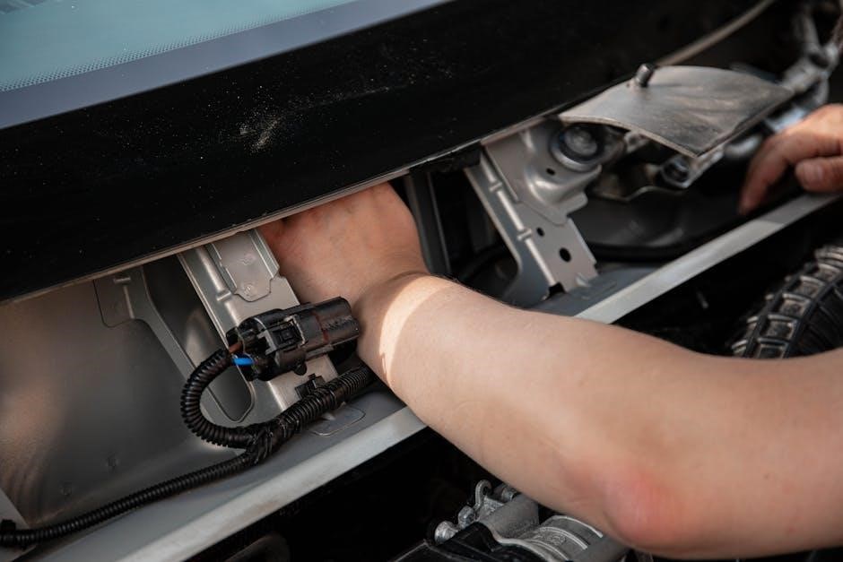
Connecting to the Tow Vehicle
Establishing a secure connection to the tow vehicle’s electrical system is crucial․ Begin by locating a suitable 12-volt power source‚ often found behind the dashboard or under the hood․ This wire should be fused for protection․ Connect the Prodigy’s power wire (typically red) to this source․
Next‚ identify the vehicle’s brake light switch wire․ This wire provides the signal to the controller when the brakes are applied․ Connect the Prodigy’s brake light input wire (usually white) to this wire․
Finally‚ a solid ground connection is essential․ Attach the controller’s ground wire (typically black) to a clean‚ unpainted metal surface on the vehicle’s chassis․ Ensure all connections are secure and insulated to prevent shorts․ A poor ground can cause erratic behavior or a complete failure of the braking system․
Connecting to the Trailer
Connecting the Prodigy brake controller to the trailer involves utilizing the standard 7-way RV blade connector․ Ensure the trailer connector is clean and free of corrosion for optimal signal transmission․ The controller sends brake signals through the connector’s electric brake wire‚ typically blue in color․
Verify that the trailer’s electric brakes are properly wired and functioning before connecting․ Check the trailer’s brake magnets and wiring for any damage or loose connections․ A properly functioning trailer wiring harness is vital for safe towing․
Once connected‚ test the trailer brakes using the manual override function on the Prodigy controller․ This confirms that the signal is reaching the trailer brakes and that they are responding accordingly․ Inspect the trailer brake lights to ensure they illuminate when the vehicle brakes are applied․
Grounding Considerations
Proper grounding is absolutely critical for the reliable operation of the Prodigy brake controller․ A poor ground can lead to erratic braking‚ flashing error codes (like the “NC” error)‚ and overall system malfunction․ The controller requires a solid connection to the vehicle’s chassis ground․

Ensure the ground wire is securely fastened to a clean‚ unpainted metal surface on the vehicle’s frame․ Avoid grounding to plastic or body panels․ Use a ring terminal and a self-tapping screw for a robust connection․ Inspect the existing ground connections in the tow vehicle for corrosion or looseness․
If experiencing issues‚ particularly the “NC” error‚ prioritize checking and improving the ground connection․ A supplemental ground wire directly from the controller to the frame can sometimes resolve grounding-related problems․ Maintaining a strong ground ensures accurate brake signal transmission․

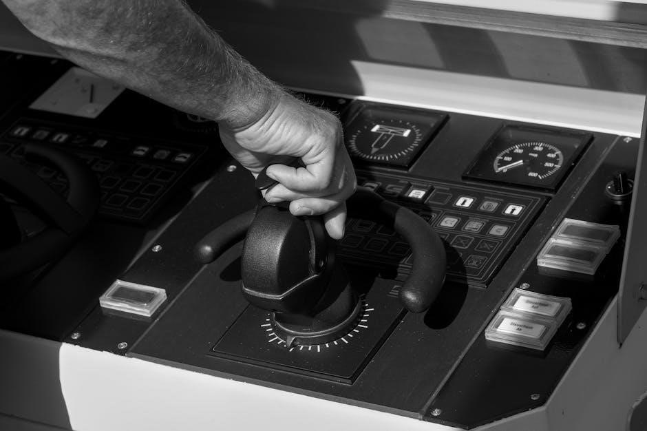
Operation and Features
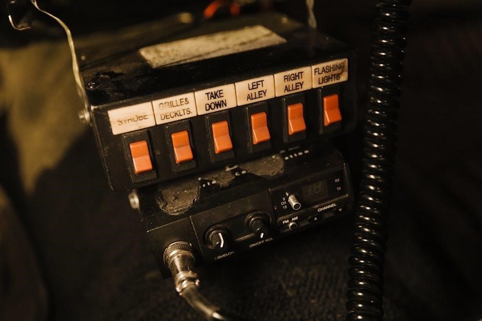
The Prodigy controller boasts proportional braking‚ a motion sensor‚ and manual override․ It automatically adjusts to terrain‚ offering smooth and responsive trailer braking performance․
Initial Setup and Calibration
Upon initial installation‚ the Prodigy brake controller requires a calibration process to ensure optimal performance․ Begin by verifying all wiring connections are secure and correct‚ referencing the wiring diagram․ With the vehicle and trailer connected‚ power on the controller․ The controller will initiate a learning mode‚ prompting you to manually apply the trailer brakes using the manual override lever․
Gradually increase brake pressure‚ holding it at a moderate level for several seconds․ The controller learns the maximum braking output of your trailer during this phase․ Repeat this process two to three times‚ ensuring consistent pressure each time․ The controller automatically adjusts to varying terrains‚ eliminating the need for manual level adjustments․ Following calibration‚ perform a test drive to confirm proper braking functionality and responsiveness․ If erratic behavior is observed‚ repeat the calibration process․
Proportional Braking Explained
Proportional braking is a key feature of the Prodigy controller‚ ensuring smooth and controlled stops․ Unlike traditional brake controllers‚ it doesn’t apply a fixed voltage; instead‚ it dynamically adjusts braking force based on the tow vehicle’s deceleration․ Utilizing motion sensor (P2) or inertial sensor (P3) technology‚ the controller accurately detects when and how quickly you are slowing down․
This information is then used to apply the appropriate amount of braking force to the trailer‚ mirroring the vehicle’s deceleration․ The result is a more natural and responsive braking experience‚ reducing trailer sway and improving overall safety․ The P3’s inertial sensor enhances this by sensing deceleration directly‚ providing even more precise control․ This system eliminates the need for manual adjustments‚ adapting to varying terrains and load conditions automatically․
Motion Sensor Technology
The Prodigy P2 utilizes advanced motion sensor technology‚ similar to systems found in the aerospace industry‚ to deliver responsive and effective trailer braking․ This sensor detects changes in the tow vehicle’s momentum – acceleration and deceleration – to determine the appropriate braking force needed for the trailer․ It doesn’t rely on the vehicle’s brake light switch‚ offering a more accurate and consistent signal․
The sensor measures the rate of change in speed‚ translating this into a corresponding voltage sent to the trailer brakes․ This proportional response ensures smoother stops and reduces the risk of trailer sway․ Because it’s reactive to vehicle movement‚ the P2 automatically adjusts to varying terrains and driving conditions‚ eliminating the need for manual adjustments․ This technology contributes to a safer and more controlled towing experience․
Manual Override Function
The Prodigy brake controller is equipped with a manual override function‚ providing the driver with independent control over the trailer brakes․ This feature is crucial for testing the trailer brakes‚ performing emergency stops‚ or maintaining control in situations where the proportional braking system isn’t sufficient․
Activating the manual override involves moving the control lever to the left․ Even when the “NC” error code is displayed‚ the manual brake lever retains some functionality‚ though potentially reduced – reports suggest around 50% effectiveness in certain scenarios․ This allows for a degree of braking power even with controller issues․ It’s important to note that using the manual override disengages the proportional braking system‚ requiring the driver to manually modulate the trailer brakes․ Regular testing of this function is recommended to ensure its proper operation․
Adjusting Brake Sensitivity
The Prodigy P2 and P3 brake controllers are designed to automatically adjust to varying terrains and braking demands‚ often eliminating the need for manual sensitivity adjustments․ However‚ understanding the system’s responsiveness is key to optimal performance․ The P2 model‚ specifically‚ features a self-adjusting system‚ leveraging motion sensor technology akin to aerospace applications․
While a manual knob for sensitivity isn’t present‚ the controller learns your driving style and trailer characteristics over time․ The P3 utilizes an inertial sensor‚ detecting deceleration to generate a proportional braking output․ If you experience erratic braking‚ ensure proper installation and grounding․ Though not a direct adjustment‚ verifying trailer brake functionality and load distribution can indirectly influence the controller’s perceived sensitivity․ Consistent‚ smooth driving habits also contribute to the controller’s learning process․
Troubleshooting Common Issues
Common problems include the flashing “NC” error‚ no brake response‚ erratic braking‚ and controller-trailer recognition failures; proper grounding and wiring are crucial for resolution․
Flashing “NC” Error Code
The flashing “NC” error on the Prodigy controller indicates a No Connection issue‚ though it can be misleading․ Reports from the TrailManor Owners Forum suggest the trailer lights may still function normally even when the “NC” code is displayed‚ potentially ruling out a simple trailer grounding problem․
This error doesn’t always signify a complete wiring failure․ The controller might intermittently detect a connection and then lose it‚ causing the random flashing․ Even with the “NC” code present‚ the manual brake lever may still exert some control‚ albeit reduced – approximately 50% effectiveness has been observed in some cases․
Troubleshooting steps include: verifying all connections at the controller‚ the 7-way connector‚ and the trailer wiring; inspecting the wiring harness for damage or corrosion; and ensuring the vehicle battery is fully charged․ If the issue persists‚ a deeper dive into the controller’s internal circuitry may be necessary․
No Brake Response
Complete lack of brake response with your Prodigy controller requires systematic troubleshooting․ First‚ confirm the controller is receiving power and is properly calibrated․ Verify the emergency break-away cable is securely connected to both the tow vehicle and the trailer – a disconnected cable can disable trailer brakes․
Next‚ meticulously inspect all wiring connections‚ from the controller to the 7-way connector and then to the trailer’s brake wiring․ Look for corrosion‚ loose connections‚ or damaged wires․ Ensure the trailer’s brake drums or rotors are in good condition and aren’t seized․
Consider these points: The controller’s output signal might be reaching the trailer‚ but the trailer’s brakes themselves are failing to engage․ Consult the trailer manufacturer’s documentation for brake-specific troubleshooting․ A faulty trailer brake module could also be the culprit․
Erratic Braking Behavior
Erratic braking – jerking‚ inconsistent stopping power‚ or uneven brake application – indicates a potential issue with the controller’s calibration or the trailer’s braking system․ Begin by re-calibrating the Prodigy controller‚ ensuring the trailer is level and on a firm surface․ Verify the motion sensor is functioning correctly; obstructions or damage can cause inaccurate readings․
Inspect the trailer’s brake drums or rotors for uneven wear‚ warping‚ or contamination․ Check the wheel bearings for excessive play‚ as this can affect brake performance․ Examine the trailer wiring for intermittent shorts or open circuits‚ which can disrupt the signal to the brakes․
Consider this: Uneven brake shoe or pad wear on the trailer can also cause erratic behavior․ A faulty ground connection can introduce noise into the system‚ leading to unpredictable braking․
Controller Not Recognizing Trailer
If the Prodigy controller fails to recognize the trailer‚ indicated by a lack of response during calibration or operation‚ several factors could be at play․ First‚ meticulously check all wiring connections between the tow vehicle and the trailer‚ ensuring a secure and corrosion-free connection․ Verify the trailer’s breakaway cable is properly connected and functional․
A common issue is a faulty ground connection․ Inspect the ground wire at both the tow vehicle and trailer‚ cleaning any corroded surfaces․ Confirm the trailer lights are functioning correctly; if they aren’t‚ it suggests a wiring problem․
Troubleshooting tip: The flashing “NC” error code can sometimes mimic a trailer recognition issue․ Ensure the controller is compatible with the trailer’s electrical system (e․g․‚ number of axles)․
LED Indicator Light Meanings
The Prodigy brake controller utilizes LED indicator lights to communicate its status and any potential issues․ A solid green light signifies normal operation‚ indicating the controller is properly calibrated and functioning as intended․ A flashing green light during initial setup denotes the controller is in learning mode‚ recording brake application․
A flashing “NC” (No Connection) light is a critical indicator․ It suggests a potential problem with the trailer’s wiring‚ ground connection‚ or the controller’s ability to detect the trailer․ However‚ functioning trailer lights while the “NC” light flashes may indicate the issue isn’t grounding related․
A red light signals a system fault‚ requiring immediate attention․ Consult the full manual for specific red light codes․ Remember to always refer to the official Tekonsha documentation for the most accurate and up-to-date LED interpretations․

Advanced Features & Maintenance
Prodigy controllers offer reverse braking and user-customizable settings․ Regular cleaning‚ proper storage‚ and potential firmware updates ensure optimal performance and longevity of the unit․
Reverse Braking Functionality
The Tekonsha Prodigy P3 model incorporates a sophisticated inertial sensor that enables proportional braking even when the vehicle is in reverse․ This feature is a significant safety enhancement‚ particularly when maneuvering trailers in tight spaces or backing down ramps․ Unlike the P2‚ which may require manual adjustment or not offer this capability‚ the P3 automatically applies the trailer brakes proportionally to the vehicle’s deceleration during reverse movement․
This functionality is crucial for maintaining control and preventing runaway situations․ The controller senses deceleration and generates an output based on the rate of slowing down‚ mirroring the proportional braking experienced during forward travel․ Users should familiarize themselves with how this feature operates to ensure safe and effective trailer control in reverse․ It’s important to note that proper installation and calibration are essential for the reverse braking function to work correctly․
User Settings and Customization
The Prodigy brake controllers‚ particularly the P3‚ offer limited user-adjustable settings‚ differing from some other brake control models․ Notably‚ the P2 and P3 are designed to largely self-adjust‚ minimizing the need for manual knob adjustments․ However‚ understanding the controller’s behavior and recognizing when recalibration might be necessary is key to optimal performance․
While extensive customization isn’t a primary feature‚ users can influence braking performance through proper initial setup and calibration․ The controllers adapt to varying terrains and towing conditions automatically‚ utilizing motion or inertial sensor technology․ Troubleshooting scenarios‚ like the flashing “NC” error‚ may require resetting the controller․ Refer to the full instruction manual for detailed guidance on interpreting LED indicators and addressing potential issues․ Firmware updates‚ if available‚ could introduce new functionalities or improvements․
Cleaning and Storage
Maintaining your Prodigy brake controller is relatively straightforward‚ requiring only periodic cleaning to ensure optimal performance and longevity․ Regularly wipe down the controller’s exterior with a slightly damp‚ soft cloth to remove dust and grime․ Avoid using harsh chemicals or abrasive cleaners‚ as these could damage the unit’s finish or internal components․
When not in use‚ store the controller in a clean‚ dry location‚ protected from extreme temperatures and humidity․ A padded case or original packaging is ideal for preventing physical damage during storage․ Disconnect the controller from the tow vehicle’s electrical system before long-term storage to prevent battery drain․ Periodically inspect the wiring connections for corrosion or damage‚ addressing any issues before reinstalling the controller․ Proper storage contributes to the controller’s reliable operation for years to come․
Firmware Updates (If Applicable)
Currently‚ not all Prodigy brake controller models support firmware updates․ However‚ Tekonsha may release updates for certain P3 models to enhance performance or address compatibility issues․ Check the Tekonsha website (https://www․etrailer․com/) periodically for available updates and instructions specific to your controller’s serial number․
If an update is available‚ it typically involves downloading a file to a compatible USB drive and connecting the drive to the controller․ Follow the on-screen prompts carefully during the update process‚ ensuring the controller has a stable power supply․ Interrupting the update can potentially damage the unit․ Always read the update instructions thoroughly before proceeding․ If you are uncomfortable performing the update yourself‚ consult a qualified technician․ Keeping your controller’s firmware current can optimize its functionality․
Safety Precautions
Prioritize safety when installing and operating your Prodigy brake controller․ Always disconnect the vehicle’s battery before commencing any wiring work to prevent short circuits and electrical shock․ Ensure all connections are secure and properly insulated․ Incorrect wiring can lead to brake malfunction and potentially cause accidents․
Regularly inspect the controller‚ wiring‚ and trailer connections for damage․ Never exceed the trailer’s maximum braking capacity․ Perform test stops in a safe‚ open area to verify proper brake function before each trip․ Familiarize yourself with the controller’s manual override function and use it cautiously in emergency situations․ Improper adjustment or use can compromise braking performance․ Always adhere to local traffic laws and safe towing practices․