
Navigating the transition to solar power begins with understanding the installation process; readily available diagrams and PDF guides offer crucial step-by-step instructions for homeowners and installers alike.
Comprehensive resources, like those detailing commercial and industrial installations, emphasize proper connections between components – batteries, panels, grid, generation sources, and loads – for optimal performance.
Furthermore, guides highlight the importance of mechanical design, wind load considerations, and adherence to building regulations, ensuring a safe and efficient photovoltaic (PV) system installation.
Detailed manuals and online resources, including YouTube tutorials, provide valuable insights into system monitoring, troubleshooting, and regulatory compliance, empowering users throughout the process.
Benefits of Solar Energy
Embracing solar energy offers a multitude of advantages, extending far beyond simply reducing electricity bills. The shift towards photovoltaic (PV) systems, guided by detailed solar panel installation diagrams and PDF manuals, unlocks significant economic and environmental benefits for homeowners and businesses.
Financially, solar installations provide long-term cost savings, shielding consumers from fluctuating energy prices and potentially generating income through net metering programs. Access to resources like step-by-step guides empowers informed decision-making, optimizing system performance and return on investment.
Environmentally, solar power is a clean, renewable energy source, drastically reducing reliance on fossil fuels and minimizing carbon emissions. This contributes to a healthier planet and a more sustainable future. Understanding system components, as illustrated in installation guides, ensures responsible energy production.
Moreover, solar energy enhances energy independence, lessening vulnerability to grid outages and promoting self-sufficiency. The availability of comprehensive documentation, including commercial installation manuals, fosters confidence and facilitates successful implementation.
Ultimately, investing in solar is an investment in a brighter, cleaner, and more secure energy future.
Understanding Solar Panel Systems
Solar panel systems are comprised of interconnected components working harmoniously to convert sunlight into usable electricity. A crucial first step in comprehending these systems is utilizing a detailed solar panel installation diagram or PDF guide, which visually breaks down the process.
These diagrams typically illustrate the flow of energy from the photovoltaic (PV) modules – the panels themselves – through the inverter, which converts DC electricity to AC. Understanding the role of each component, as outlined in installation manuals, is paramount.
Furthermore, systems often include mounting hardware for secure roof attachment, and wiring for connecting panels to the inverter and ultimately, to the grid or load center. Commercial installation guides emphasize proper connections for optimal performance.
Key considerations include system size, panel orientation, shading analysis, and adherence to local building codes. Resources like BRE digests provide guidance on mechanical installation and wind load calculations, ensuring system longevity.
Ultimately, a clear understanding of system architecture, facilitated by visual aids, is essential for successful installation and operation.

Essential Components of a Solar Panel System
Detailed solar panel installation diagrams and PDF guides clearly illustrate the vital parts: panels, inverters, and mounting hardware, ensuring a complete system understanding.
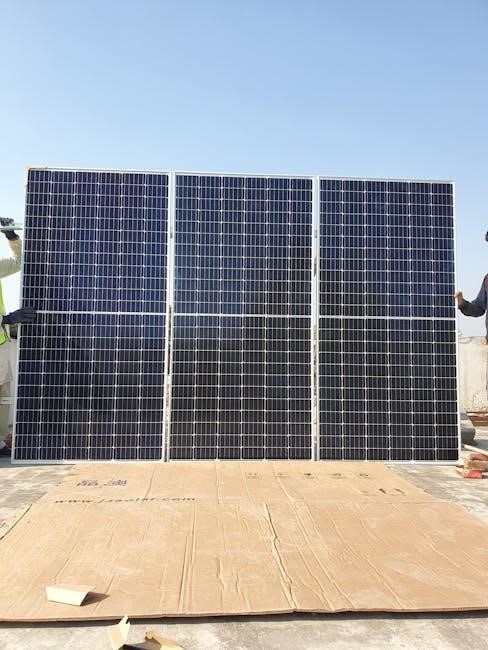
Solar Panels (Photovoltaic Modules)
Photovoltaic (PV) modules, commonly known as solar panels, are the fundamental building blocks of any solar energy system, and solar panel installation diagrams in PDF format meticulously detail their placement and connection.
These diagrams showcase how panels convert sunlight directly into direct current (DC) electricity, emphasizing the importance of proper orientation and tilt angles for maximizing energy production.
Installation guides often feature schematics illustrating series and parallel wiring configurations, crucial for achieving the desired voltage and current output. Understanding these configurations, as presented in the diagrams, is paramount for efficient system performance.
Furthermore, the PDFs highlight the importance of selecting panels with appropriate voltage and power ratings, compatible with the chosen inverter and overall system design. They also address considerations like shading and temperature effects on panel efficiency, providing guidance for optimal placement to mitigate these factors.
Detailed specifications, often included within the diagrams, outline the panel’s electrical characteristics, dimensions, and warranty information, ensuring informed decision-making during the installation process.
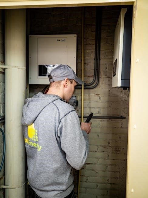
Inverters (String, Microinverters, Power Optimizers)
Inverters are critical components transforming the DC electricity generated by solar panels into alternating current (AC) electricity usable by homes and businesses; solar panel installation diagrams in PDF format illustrate their integration.
These diagrams differentiate between various inverter types – string inverters, microinverters, and power optimizers – detailing their respective advantages and disadvantages. String inverters, the most common, connect to a series of panels, while microinverters attach to individual panels.
PDF guides emphasize the importance of matching inverter capacity to the solar array’s output, preventing clipping and maximizing energy harvest. Wiring schematics clearly demonstrate DC-to-AC conversion and grid connection procedures.
Furthermore, diagrams highlight safety features like ground fault protection and anti-islanding mechanisms, crucial for preventing hazards and ensuring grid stability. They also illustrate the role of power optimizers in mitigating shading effects and maximizing individual panel performance.
Detailed specifications within the diagrams outline inverter efficiency, voltage ranges, and communication capabilities, aiding in informed selection and proper installation.
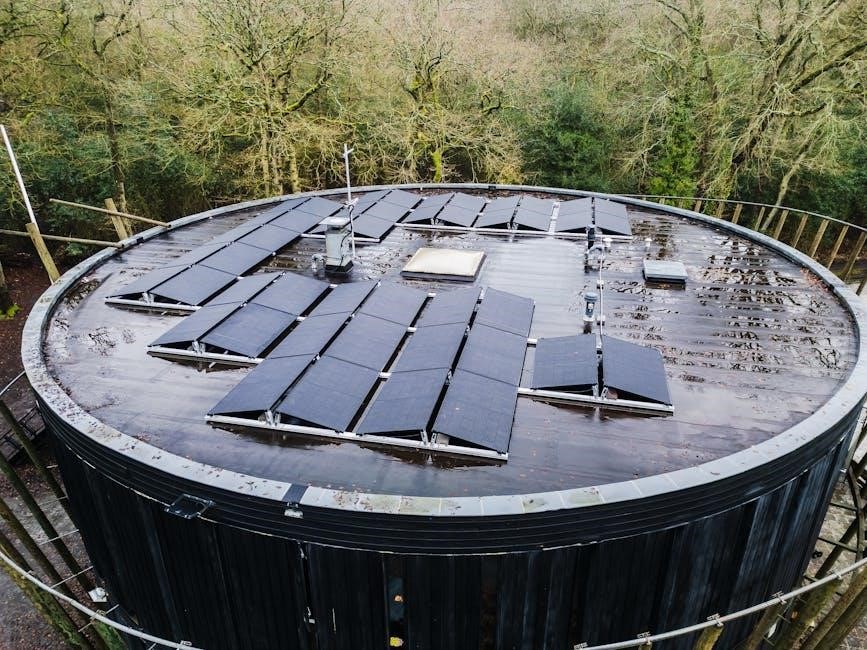
Mounting Hardware
Securely attaching solar panels to rooftops or ground mounts requires robust mounting hardware, meticulously detailed in solar panel installation diagrams available as PDF documents. These diagrams showcase various mounting systems tailored to different roof types – pitched, flat, and tile.
They illustrate the use of rails, clamps, flashing, and standoff mounts, emphasizing proper waterproofing techniques to prevent leaks. PDF guides highlight the importance of wind load calculations and adherence to local building codes, ensuring structural integrity.
Detailed schematics demonstrate the correct sequence for installing mounting components, including anchoring to rafters or trusses. Diagrams also depict ground-mounted systems, showcasing concrete foundations and racking structures.
Furthermore, they specify appropriate hardware materials – aluminum, stainless steel – to withstand environmental conditions and prevent corrosion. Correct torque specifications for bolts and screws are crucial, as shown in the diagrams.
Comprehensive guides also address considerations for snow loads and seismic activity, ensuring long-term system reliability and safety.
Safety Precautions During Installation
Detailed solar panel installation diagrams in PDF format emphasize electrical and roof safety; proper grounding, PPE, and fall protection are paramount during every phase.
Electrical Safety
Crucially, solar panel installation diagrams and accompanying PDF guides consistently prioritize electrical safety, stressing the importance of disconnecting power sources before commencing work.
These resources detail proper grounding techniques to mitigate shock hazards, emphasizing the need for qualified personnel to handle all electrical connections and wiring.
Specifically, manuals like those for Sol-Ark systems warn against exceeding MPPT voltage limits (550V) and highlight the significance of correctly installing Current Transformers (CTs) to avoid inaccurate readings.
Furthermore, they underscore the necessity of adhering to local electrical codes and utilizing appropriate personal protective equipment (PPE), including insulated gloves and safety glasses.
Alarm states, as detailed in system documentation, must be promptly investigated using the alarms menu, and any damaged wiring or components should be immediately replaced to prevent potential hazards.
Always remember that improper electrical work can lead to severe injury or fire, making adherence to safety protocols non-negotiable.
Roof Safety
Solar panel installation diagrams and PDF guides frequently emphasize roof safety as paramount, detailing precautions to prevent falls – a leading cause of injury during installations.
Guides, such as those referencing BRE Digests 489 and 495, highlight the importance of assessing roof structural integrity before mounting any equipment, ensuring it can bear the added weight.
Proper fall protection equipment, including harnesses, lifelines, and guardrails, is consistently recommended and often mandated by safety regulations.
Installers should be trained in safe roof access techniques, including ladder safety and proper footwear, and avoid working in adverse weather conditions like high winds or rain.
Careful consideration must be given to the roof’s pitch and material, as these factors influence the choice of mounting hardware and installation procedures.
Regular inspections of the roof and mounting system are crucial to identify and address any potential hazards, ensuring long-term safety and system reliability.

Pre-Installation Assessment
Detailed diagrams and PDF guides stress thorough site surveys, including shading analysis and roof condition assessments, to optimize system performance and longevity.
These evaluations determine panel placement, identify potential obstructions, and ensure the roof’s structural integrity supports the solar array’s weight.
Site Survey and Shading Analysis
A comprehensive site survey, often visually represented in diagrams within installation PDF guides, is the foundational step before any solar panel installation. This assessment meticulously evaluates the property’s solar resource potential.
Crucially, shading analysis identifies obstructions – trees, buildings, chimneys – that could diminish sunlight reaching the panels, impacting energy production. Tools and techniques range from visual inspections to specialized solar pathfinder devices and software modeling.
Detailed diagrams illustrate the sun’s path throughout the year, pinpointing periods of shading and allowing for strategic panel placement to maximize sunlight exposure. Understanding shading patterns is vital for accurate system sizing and performance predictions.
Furthermore, the survey documents roof orientation, tilt, and available space, informing the optimal array configuration. Accurate data collection during this phase directly translates to a more efficient and cost-effective solar energy system.
Proper analysis ensures long-term energy yield and return on investment.
Roof Condition Assessment
Prior to solar panel installation, a thorough roof condition assessment is paramount, often detailed within installation PDF guides and accompanying diagrams. This evaluation determines the roof’s structural integrity and suitability for supporting the added weight of the solar array.
Inspectors meticulously check for existing damage – leaks, rot, weakened shingles – and assess the remaining lifespan of the roofing material. BRE Digests, referenced in photovoltaic installation guides, provide guidance on wind load considerations and mechanical installation best practices.
Addressing any pre-existing issues is crucial; repairing or replacing a roof after panel installation is significantly more costly and complex. Diagrams often illustrate proper flashing techniques to prevent water intrusion around mounting hardware.
The assessment considers roof type (asphalt shingles, tile, metal) as different materials require specific mounting solutions. A structurally sound roof ensures the long-term safety and performance of the solar energy system, protecting your investment.
Ultimately, a solid foundation is key.

Detailed Installation Steps
Following a diagram or PDF guide, mounting systems are installed first, then panels are placed and connected, and finally, the inverter is installed with precise wiring.
Mounting System Installation
Crucially, the mounting system installation, often detailed in a solar panel installation diagram PDF, forms the foundation for a secure and long-lasting solar array. This phase begins with a thorough assessment of the roof’s structural integrity, ensuring it can bear the added weight of the panels and mounting hardware.
Next, the chosen mounting hardware – rails, brackets, and flashing – are carefully installed, adhering to manufacturer specifications and local building codes; Proper flashing is paramount to prevent water intrusion and potential roof damage. Diagrams often illustrate correct attachment points and torque settings for optimal stability.
Furthermore, BRE Digests 489 and 495 provide guidance on wind load calculations and mechanical installation best practices for roof-mounted systems. Ensuring the mounting system is level and securely fastened is vital for maximizing sunlight capture and withstanding environmental stresses. A well-installed mounting system guarantees the longevity and efficiency of the entire solar installation.
Solar Panel Placement and Connection
Following mounting system installation, precise solar panel placement and connection are critical, often visually guided by a solar panel installation diagram PDF. Panels are positioned according to the site survey, maximizing sunlight exposure and minimizing shading throughout the day.
Securely attaching the panels to the mounting rails is paramount, utilizing appropriate clamps and hardware. Diagrams typically illustrate correct panel orientation and spacing for optimal performance. Once mechanically secured, the electrical connections begin, linking panels in series or parallel configurations, depending on the system design.
Careful attention to polarity is essential to avoid damaging the panels or inverter. DC wiring is then routed from the panels to the inverter, utilizing weatherproof connectors and conduit. A step-by-step guide ensures correct wiring sequences, minimizing errors and maximizing energy production. Proper connections are vital for a safe and efficient system.
Inverter Installation and Wiring
The inverter, a central component, converts DC power from the panels to usable AC electricity; its installation and wiring are detailed in a solar panel installation diagram PDF. Secure mounting, often near the electrical service panel, is crucial, ensuring adequate ventilation to prevent overheating.

Wiring involves connecting the DC output from the solar panels to the inverter’s DC input terminals, strictly adhering to polarity. Subsequently, the AC output is connected to the home’s electrical panel, typically through a dedicated breaker. Diagrams emphasize proper grounding procedures for safety.
Commercial systems may utilize multiple inverters or advanced technologies like microinverters or power optimizers, each requiring specific wiring configurations. Careful attention to voltage and current ratings is vital. Following the PDF guide ensures correct connections and safe operation.

Electrical Connections and Wiring Diagrams
Detailed solar panel installation diagram PDFs illustrate DC wiring from panels to the inverter, and AC wiring connecting to the grid or load center, ensuring safety.
DC Wiring (Panel to Inverter)
Crucially, solar panel installation diagram PDFs meticulously detail DC wiring procedures, emphasizing the connection between photovoltaic (PV) modules and the inverter. These diagrams illustrate proper polarity – positive to positive, negative to negative – to prevent damage and ensure efficient energy transfer.
Furthermore, they specify appropriate wire gauges based on current and distance, minimizing voltage drop and maximizing system performance. Diagrams often highlight the use of weatherproof connectors and conduit for outdoor runs, safeguarding against environmental factors.
Importantly, they demonstrate series and parallel configurations of panels, explaining how these affect voltage and current levels reaching the inverter. Safety is paramount; diagrams stress the need for DC disconnect switches for maintenance and emergency shutdowns. Monitoring MPPT voltages, ensuring they don’t exceed 550V, is also a key element shown in these guides.
Finally, these resources often include detailed schematics showing grounding requirements for DC circuits, protecting against electrical hazards and ensuring compliance with electrical codes.
AC Wiring (Inverter to Grid/Load Center)
Solar panel installation diagram PDFs provide comprehensive guidance on AC wiring, detailing the connection between the inverter and the electrical grid or load center. These diagrams emphasize adherence to local electrical codes and safety regulations throughout the process.
Crucially, they illustrate the use of dedicated circuit breakers sized appropriately for the inverter’s output, protecting against overcurrents. Diagrams often showcase the necessity of grounding the inverter and AC disconnect switch for safety and proper operation.
Furthermore, they depict the wiring pathway, often requiring conduit for protection, and highlight the importance of labeling all components clearly. Monitoring power flow using CT sensors (HM, LD) is often illustrated, noting that opposing values indicate incorrect installation.
Detailed schematics show how to connect the inverter to the load center, ensuring proper phase alignment and voltage compatibility. Finally, these resources stress the importance of professional inspection and approval before energizing the system.
System Monitoring and Performance
Solar panel installation diagram PDFs often detail monitoring systems, explaining how to interpret data and troubleshoot common issues for optimal energy production.
Understanding HM and LD power measurements, alongside alarm states, is crucial for identifying and resolving performance discrepancies efficiently.
Understanding System Monitoring Data
Solar panel installation diagram PDFs frequently include sections dedicated to interpreting system monitoring data, a critical aspect of ensuring optimal performance and identifying potential issues. These diagrams often illustrate how key metrics are displayed and analyzed, allowing users to quickly assess system health.
Specifically, understanding terms like ‘HM’ (power measured by external CT sensors – L1, L2 & L3) and ‘LD’ (power measured by the internal sensor on the GRID terminal – L1, L2 & L3) is vital. Discrepancies between HM and LD values can indicate incorrect CT installation, a common issue addressed in detailed manuals.
Furthermore, monitoring systems track MPPT voltages, with alarms triggered if these exceed 550V, safeguarding the inverter. Analyzing alarm menus and understanding the meaning of different alarm states is essential for proactive troubleshooting. Regular review of this data, guided by the installation diagram, empowers users to maximize energy yield and maintain system reliability.
Troubleshooting Common Issues
Solar panel installation diagram PDFs often dedicate sections to troubleshooting, recognizing that even with careful installation, issues can arise. These guides typically begin with a systematic approach, referencing alarm states and error codes displayed on the inverter or monitoring system.
For instance, a “Red Alarm” state, as highlighted in commercial installation manuals, prompts users to consult the alarms menu for specific details. Common problems include incorrect CT sensor installation, indicated by opposing Grid or HM values, and exceeding MPPT voltage limits (above 550V).
The diagrams themselves aid in identifying wiring errors or component failures. By visually tracing connections and comparing them to the schematic, installers can quickly pinpoint the source of the problem. Resources like YouTube tutorials supplement these PDFs, offering visual guidance for resolving frequently encountered issues, ensuring system uptime and efficiency.

Regulatory Compliance and Permits
Solar panel installation diagram PDFs rarely detail specific permitting processes, but implicitly emphasize the need for adherence to local regulations. These diagrams showcase system configurations that must comply with electrical codes and building standards, often requiring inspections at various stages.
Guides referencing industry experience, like the updated Photovoltaics in Buildings guide, reflect evolving regulations and best practices. While the mechanical design isn’t always within the scope of the PDF, compliance with wind load and mechanical installation standards (BRE Digests 489 & 495) is crucial.
Successful installations necessitate obtaining necessary permits before commencing work. Understanding local authority requirements, often found separately from the installation diagrams, is paramount to avoid fines and ensure a legally compliant, safe, and fully operational solar energy system.